Line follower robots were one of the earliest automatic guided robots. They can follow a line marked on a contrasting background, usually a black line on a white surface or a white line on a black surface. Usually, the line follower robot works on a closed-loop feedback algorithm where the feedback from the line sensor is used by the controller for correcting the path of the robot. The sensors are usually LED/LDR, LED/Photodiode, or LED/Phototransistor pairs, and the controller is an electronic circuit that executes the desired feedback algorithm. Gear motors are used for driving the robotic wheels.
Line Follower Robot Circuit Principle
This circuit mainly consists of an 8051 microcontroller, two IR sensors, motors, and motor driver IC (embedded in a module). The line follower robot needs a mechanical arrangement of the chassis. I have used a 4WD Acrylic chassis. The two IR sensors are mounted on the front of the robot facing the diodes facing towards Earth.
When the robot is placed on the fixed path, it follows the path by detecting the line. The robot's direction of motion depends on the two sensors' outputs. When the two sensors are on the line of the path, the robot moves forward. If the left sensor moves away from the line, the robot moves towards the right. Similarly, if the right sensor moves away from the path, the robot moves towards its left. Whenever the robot moves away from its path it is detected by the IR sensor.
IR sensor consists of an IR transmitter and IR receiver on aboard. When the vehicle is moving on a black line, IR rays are continuously absorbed by the black surface and there is no reflected ray making output high. Whenever the robot moves out to the white surface, it starts reflecting the IR rays and making the output low. Thus depending on the output of the IR sensor microcontroller indicates the motors to change their direction.
block diagram:
The emitter is simply an IR LED (Light Emitting Diode) and the detector is simply an IR photodiode. The photodiode is sensitive to IR light of the same wavelength which is emitted by the IR LED. When IR light falls on the photodiode, the resistances and the output voltages will change in proportion to the magnitude of the IR light received.
There are five basic elements used in a typical infrared detection system: an infrared source, a transmission medium, an optical component, infrared detectors or receivers, and signal processing. Infrared lasers and Infrared LEDs of specific wavelength used as infrared sources.
The three main types of media used for infrared transmission are vacuum, atmosphere, and optical fibers. Optical components are used to focus the infrared radiation or to limit the spectral response.
8051 microcontroller:
motor driver chip:
circuit diagram :
- 8051 Microcontroller
- Development Board for 8051 Microcontroller (preferred)
- 10KΩ Resistors X 2
- 10µF Capacitor
- 11.0592MHz Crystal
- 33pF Capacitors X 2
- Push Button
- Motor driver Module (L298N)
- Robot Chassis with Motors
- IR Sensors x 2
working:
Line follower robot senses white line by using sensor and then sends signals to the microcontroller. Then microcontroller drives the motor according to sensors' output.
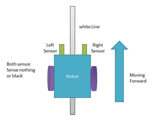
Here in this project, we are using two IR sensors pair. Suppose we are calling left sensor and right sensor of IR sensor Pair, then both left and right sensors sense nothing or black line then robot move forward.
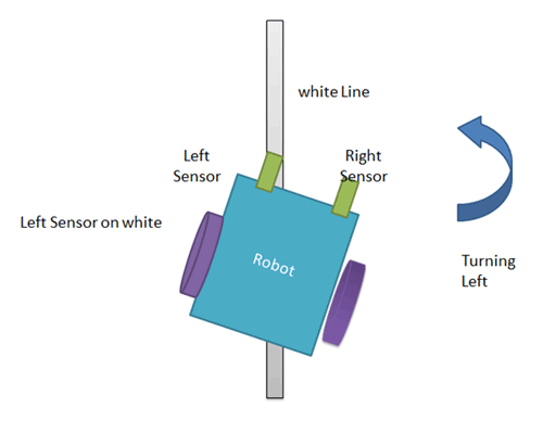
And when a left sensor senses a white line then the robot turn left side.
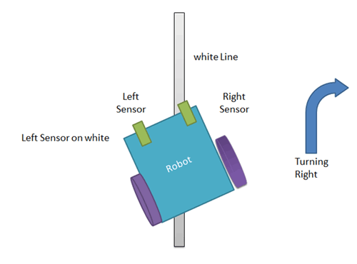
and when the left sensor senses the white line then the robot turns to the right side until both sensors come at the black line or sense nothing surface.
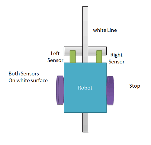
And when both sensors come on the white line, the robot stop.
code:
| #include<reg51.h> | |
| sbit mot1=P2^0; | |
| sbit mot2=P2^1; | |
| sbit mot3=P2^2; | |
| sbit mot4=P2^3; | |
| sbit s_left=P2^6; | |
| sbit s_right=P2^7; | |
| void forward (void); | |
| void backward (void); | |
| void left (void); | |
| void right (void); | |
| void forward (void) | |
| { | |
| mot1=0; | |
| mot2=1; | |
| mot3=1; | |
| mot4=0; | |
| } | |
| void backward (void) | |
| { | |
| mot1=0; | |
| mot2=1; | |
| mot3=0; | |
| mot4=1; | |
| } | |
| void left (void) | |
| { | |
| mot1=0; | |
| mot2=1; | |
| mot3=0; | |
| mot4=0; | |
| } | |
| void right (void) | |
| { | |
| mot1=0; | |
| mot2=0; | |
| mot3=1; | |
| mot4=0; | |
| } | |
| void stop (void) | |
| { | |
| mot1=0; | |
| mot2=0; | |
| mot3=0; | |
| mot4=0; | |
| } | |
| void main() | |
| { | |
| s_left=1; | |
| s_right=1; | |
| while(1) | |
| { | |
| if(s_left==0 && s_right==0) | |
| { | |
| forward(); | |
| } | |
| else if(s_left==1 && s_right==1) | |
| { | |
| stop(); | |
| } | |
| else if(s_left==0 && s_right==1) | |
| { | |
| left(); | |
| } | |
| else if(s_left==1 && s_right==0) | |
| { | |
| right(); | |
| } | |
| } | |
| } |


Post a Comment